MIL-PRF-28750F
d.
Electrical power will not be applied to the SSR during this test.
e.
Measurements and examination: SSR's shall then be examined for evidence of breaking, cracking,
chipping or flaking of the finish, or loosening of the terminals.
NOTES:
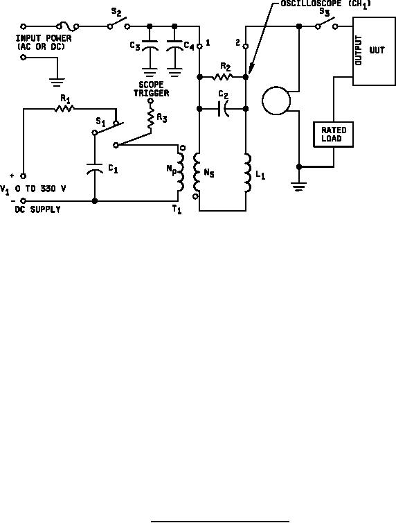
1. A mechanically or electronically operated switch may be used to replace S1.
2. The transformer windings should be bi-fillar.
3. A 50 ohm resistor replaces the equipment under test for verifying the source impedance.
4. Component values are as follows:
C1 = 2 microfarads, 1,500 volts
C2 = 0.03 microfarads, 2,000 volts
C3 = 10 microfarads, 1,000 volts
C4 = 0.01 microfarads, 1,000 volts
R1 and R2 = 100 ohms, 1 watt
R3 = 1 megohm, 0.5 watt
S1, S2, and S3 = 20 amp, SPDT switch
L1 = 50 turns, 2 inch diameter/#16 AWG
T1 = Air core transformer, 2 inch diameter/#16 AWG,
Np = 20 turns, Ns = 60 turns
FIGURE 5. Electrical system spike test setup.
34
For Parts Inquires call Parts Hangar, Inc (727) 493-0744
© Copyright 2015 Integrated Publishing, Inc.
A Service Disabled Veteran Owned Small Business