MIL-DTL-83729C
4.6.3.7.1 Alternate method for dwell time and dissymmetry.
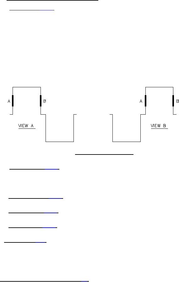
4.6.3.7.1.1 Dwell time (see 3.7.7.1). The source of oscillator or coil excitation shall be as specified (see 3.1 and
6.2.2). The oscilloscope shall be set for internal sweep with horizontal and vertical amplitudes adjusted for an
approximate pattern as shown on figure 4, using the specified coil voltage for the external trigger. The electronic
counter function selector switch is set to "time interval" and the "start trigger level" is adjusted so that the marker
appears approximately halfway on the rise slope (see point "A" in view A, figure 5). Then the "stop trigger level" is
adjusted so that the marker appears approximately halfway on the decline slope (see point "B" in view B, figure 5).
Read dwell time on counter in µx and convert to degrees. The dwell time displayed on the oscilloscope is the time of
a particular dwell as sampled on the counter. Since at 400 Hz each µs represents 1/7 of a degree, successive
samplings may not show the same number of µs on each sample due to the high accuracy of the measurement and
the slight instability of the chopper. This phenomena does not always occur; however, when it is observed, it is not a
sign of a faulty chopper. When this value varies as a dwell is sampled, the mean value should be taken as the dwell
time. Example: If the maximum counter reading is 1,196 µs and minimum counter reading is 1,190 µs, the mean
value of 1,193 µs at 400 Hz is the dwell time of the chopper and when converted from µs to degrees, equals 172
degrees.
FIGURE 5. Dwell and dissymmetry display.
4.6.3.7.1.2 Dissymmetry (see 3.7.7.2). Set switch S1 on figure 4 in D1 position. Markers should appear at points
"A" and "B" as shown on figure 5. If required, readjust markers as described in 4.6.3.7.1.1, read dwell on counter in
µs, and convert to degrees. Switch S1 shall then be switched to the D2 position. The difference in dwell readings is
the dissymmetry of the chopper. Successive samplings may not show the same number of µs on each sample due to
the high accuracy of the measurements and the slight instability of the chopper.
4.6.3.7.2 Contact bounce (see 3.7.7.3). Choppers shall be tested in accordance with the circuit shown on figure
4.6.3.7.3 Transfer time (see 3.7.7.4). Choppers shall be tested in accordance with the circuit shown on figure 2
and the waveform display of figure 3.
4.6.3.7.4 Phase angle (see 3.7.7.5). Choppers shall be tested in accordance with the circuit shown on figure 2
and the waveform display on figure 3.
4.6.3.8 Noise level (see 3.7.8). With rated coil voltage and frequency applied to coil, test the chopper in the
standard noise test circuit on figure 6, or a circuit of equivalent accuracy, with the load impedances required. The
specified rms meter may be replaced with a peak-to-peak reading vacuum-tube voltmeter (VTVM), if desired. The
output waveform of the system shall be monitored with an oscilloscope constantly to insure against the possibility of
overdriving or clipping in the amplifier. Provisions shall be made to (1) calibrate the system, and (2) to measure the
system noise level. The system noise level shall be subtracted in rms fashion from the output rms noise level to
determine the actual rms noise level.
4.6.4 Dielectric withstanding voltage (DWV) (see 3.8).
13
For Parts Inquires call Parts Hangar, Inc (727) 493-0744
© Copyright 2015 Integrated Publishing, Inc.
A Service Disabled Veteran Owned Small Business